
Jet intakes are the point in which the aerodynamic swagger of an airplane and the requirement of the engine to access to clean and stable airflow intersect. The form resembles styling, but is typically a concession that is hard to achieve between range of speed, angle-of-attack behaviour, packaging and ensuring that the face of the compressor is maintained in a good state of humour.
On the lowest level, there is an inlet that is located in the upstrain of the compressor and may have a significant effect on net thrust, though not performing any work on the flow. According to the plain language summary of NASA, much of the geometry is driven by speed, and engine net thrust is highly affected by inlet performance.
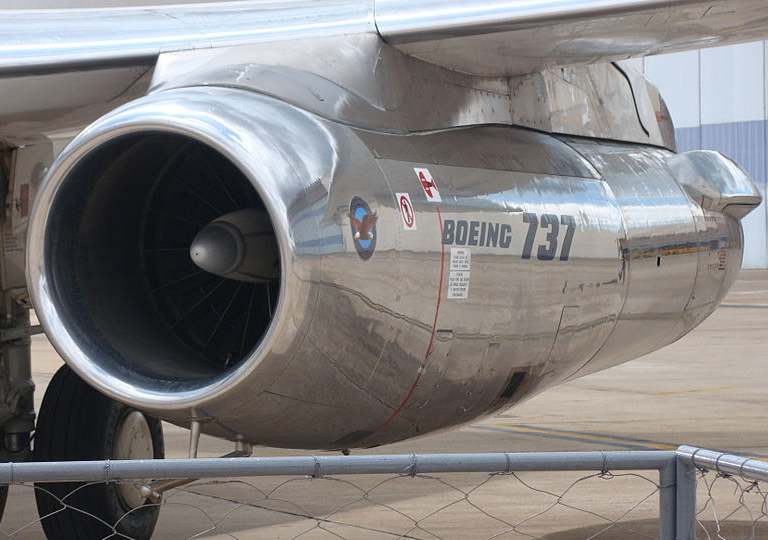
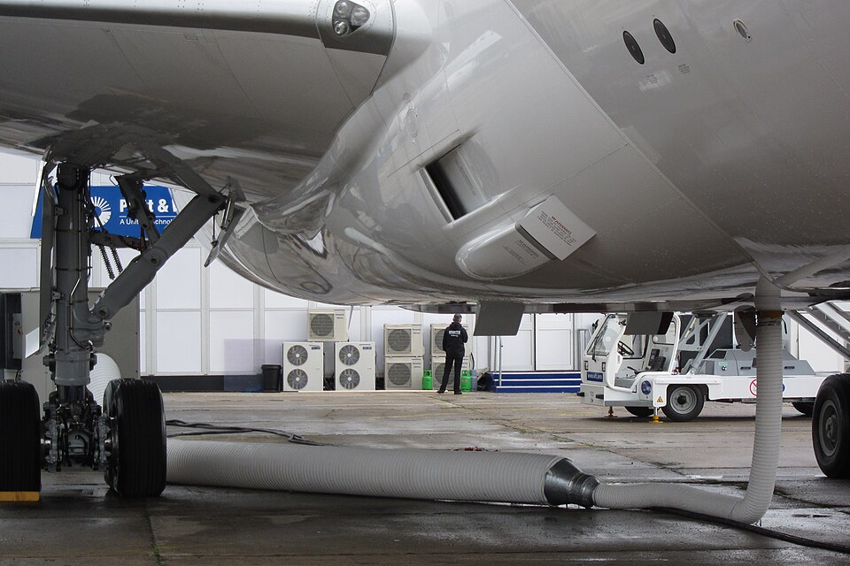
1. ThickLip Subsonic Pitot Inlet
The traditional round, straight intake of millions of airliners and trainers is streamlined in aircrafts that never fly above Mach 1. The tell that is characteristic is the comparatively thick inlet lip, which aids in keeping low-speed flow secure and fixed as the engine draws air in during taxi, takeoff and approach. NASA underlines that a continuous smooth curve of the exterior to interior shape is the common characteristic of subsonic inlets, given more emphasis on benign behavior than on tricks of high speed compression. It is the latter that appears to be the case since it is very basic: minimal shock management, minimal internal duct drama, and tend to be very efficient even as they fly at the speeds they do.
2. Sharp-Lip Supersonic Inlet
As soon as a plane enters the realm of transonic-supersonic, the inlet lip transforms. NASA observes that supersonic aircrafts have a relatively sharp lip that minimizes performance loss associated with the shock waves in addition to the inlet system that has to provide the compressor with subsonic flow. The sudden angst is not aesthetically minimalism; it is an indication that the design anticipates shocking interactions and is attempting to ensure that they do not become drag and distortion.
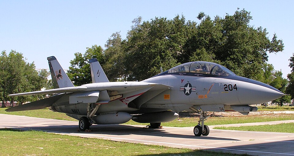
3. Variable-Ramp Rectangular Inlet (F-14/F-15 Style)
The visual characteristic of high-performance fighters based on high supersonic potential is rectangular inlets with moving ramps. NASA defines supersonic inlets that form compression shocks with flat hinged plates, forming a rectangular cross section, and identifies that this is a sort of variable-geometry technology employed on the F-14 and F-15. Code One introduces the practical why: speeds in excess of Mach 2 encourage designers to resort to more elaborate compression designs, with ramps and related doors/ducting to regulate the amount of excess airflow and shock positioning. When the engine operates effectively, the engine will experience clean pressure recovery; otherwise, instability and distortion may be the penalty.
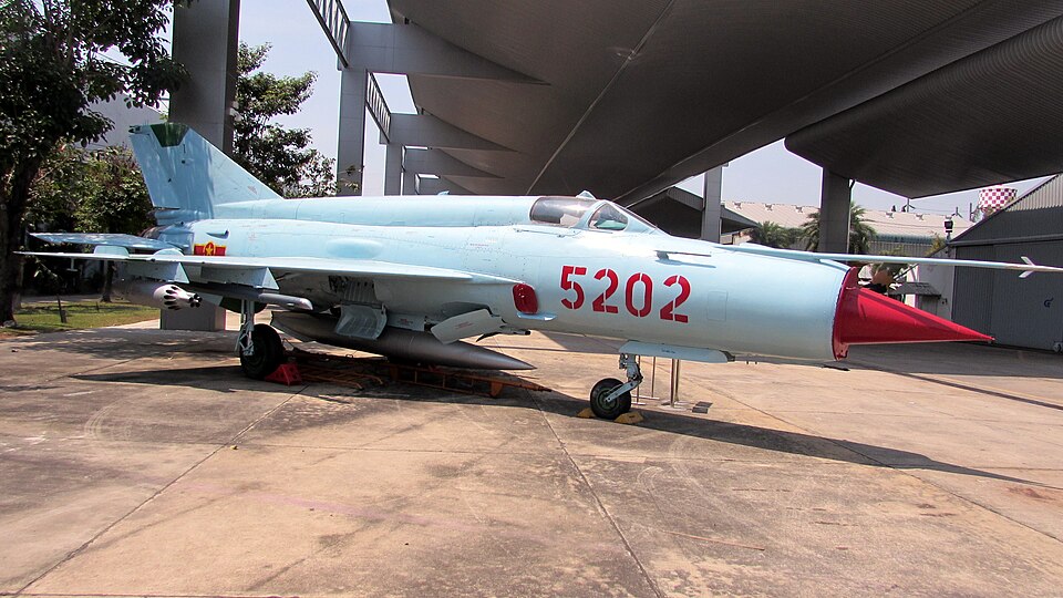
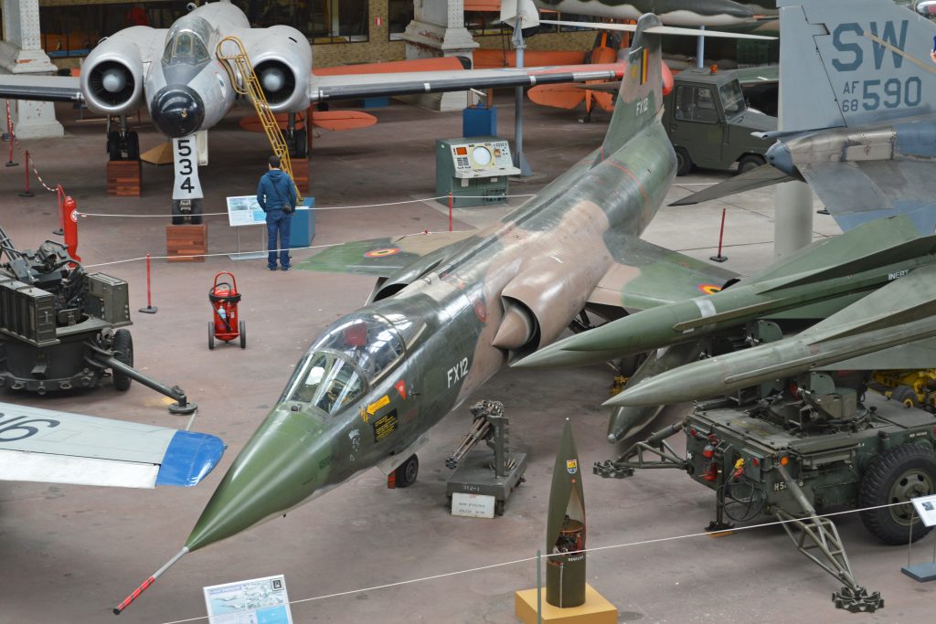
4. Translating Cone of the Inlet (MiG-21/SR-71 Family Cue)
One of the most well-known aviation supersonic signatures is the nose-cone or centerbody inlet. According to NASA, other supersonic inlets incorporate a central cone to shock the flow down thence to the compressor, which puts the compression feature at the location where the freestream is first organized. The geometry is expressive: at any rate, a moving or precisely placed cone is used to control a shock system capable of remaining functional through changes in velocity, and to maintain the compressor protected against supersonic pandemonium.
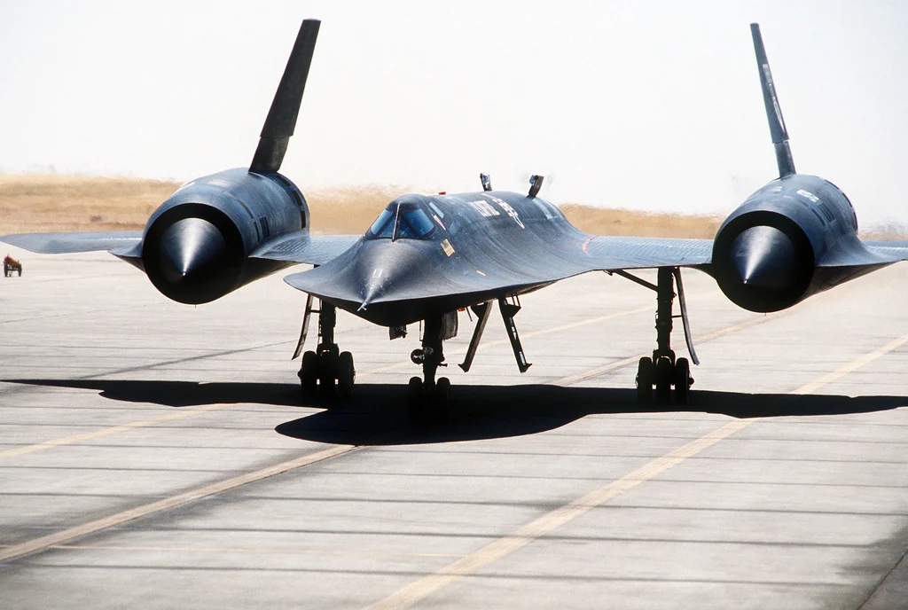
5. SR-71 Blackbird Machine 3+ Inlet That Makes Thrust
The inlets of the Blackbird are not merely a matter of feeding the engines, but an element of the high-speed math of the propulsion system. According to NASA, inlets of the Mach 3+ SR-71 aircraft are meant to be cruised at very high speed and the inlets actually generate thrust in the airplane when in flight. That alone is the essence of the SR-71 intake legend: when Mach number is very high and inlet pressure recovery, shock control and spillage control are so important that intake ceases to be an adjective.
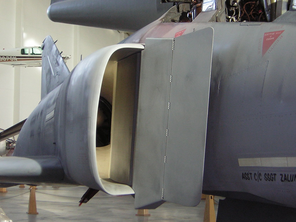
6. Splitter Plate + Diverter Gap (Typical Boundary-Layer Fix)
A lot of supersonic fighters are graphically promoting the boundary-layer management by incorporating a splitter plate or a distinguishable discontinuity between the intake and the fuselage. Code One describes the problem below: a layer of low-energy air forms at the forebody, and when that boundary layer enters the inlet may cause distortions at the engine face. The conventional method physically isolates the inlet and that layer with other apparatus that directs unwanted air to some other exit so that they cannot cause a disturbance to the compressor.
7. Bleed-Air Inlet (Hidden Ducts and Perforated Ramps)
The more advanced intakes conceal their wit in tiny holes and plumbing. Code one covers bleed systems which removes undesired boundary-layer airflow by suctioning through small holes on the compressor faces and directs it to bleed ducts in the inlet. Externally, these designs may appear to be ordinary ramped inlets; the clue is in the engineering purpose of actively cleaning, rather than pushing aside, the flow where shock/boundary-layer interactions risk becoming unstable.
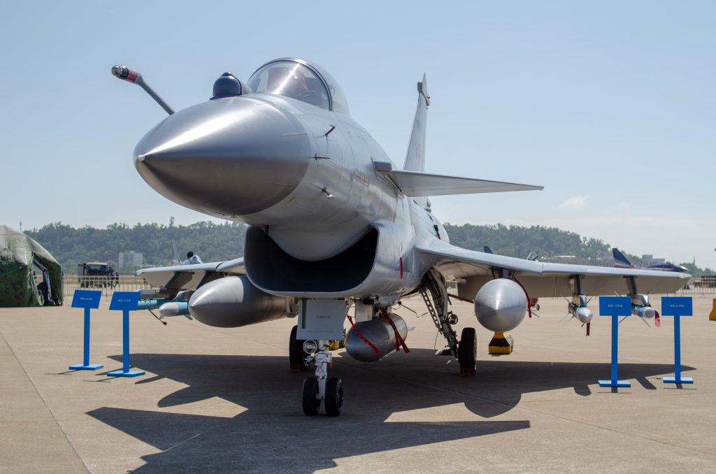
8. Diverterless Supersonic Inlet (DSI) Bump
The DSI is the new how did they get away with it? intake: no splitter plate, no complicated variable ramps, and a separate bump in front of the inlet lip. Code One tells of the lowly bump on the fuselage inlets at each inlet, which acts together with a forward-sloping cowl to deflect the flow of the boundary-layer air away from the engine at high speed. In the article, there is also a flight demonstration of an F-16 which took off and reached Mach 2.0 without any engine stalls or anomalies, and it had 164 successful afterburner lights. The functionality of the shape is convenient unification: employ a set 3D compression surface to finish various tasks that used to be performed in the older fighters with breaks, plates, ramps, and bleed plumbing.
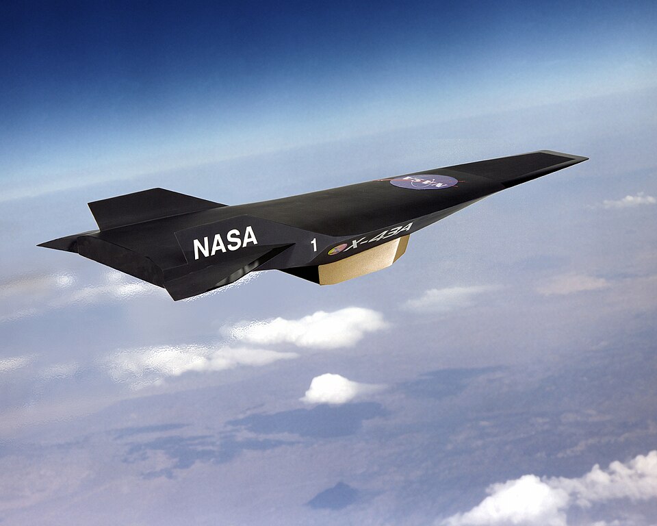
9. Hypersonic, Fuselage-Integrated Scramjet Inlet (X-43A Pattern)
At hypersonic speeds, the inlet becomes part of the airframe in a way that makes conventional “duct” thinking feel obsolete. NASA notes that scramjet inlets are highly integrated with the fuselage and that on the X-43A the inlet includes the entire lower surface of the aircraft forward of the cowl lip. It also states that the flow exiting a scramjet inlet must remain supersonic. Those constraints reshape everything: compression surfaces run hot, boundary layers grow thick, and the inlet’s job becomes managing energy and stability in a regime where shock losses are unavoidable and mechanical variable geometry is unattractive.
Across eras and mission types, intake design keeps circling back to the same non-negotiables: pressure recovery, distortion control, and behavior at the corners of the flight envelope. The legendary shapes stand out because each one is a visible answer to a specific airflow problem—sometimes solved with moving hardware, sometimes with carefully sculpted surfaces, and sometimes by letting the airframe itself become the inlet.

